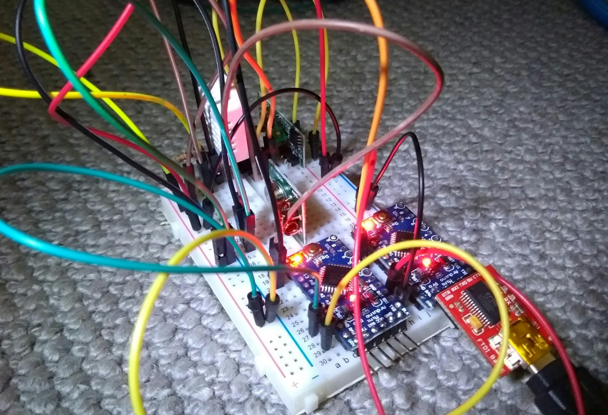
Arduino radio communication
Once again, I have ordered the wrong hardware from eBay.
This time, it was a set of 433MHz radio transceivers for "Arduino". The majority of these come with embedded circuitry for sending and receiving bits. The ones I ordered, however, did not.
The transmitter emits power when its data line is powered. The receiver emits a varying voltage, which can be ADC'd back into a value, ~1 -> ~800. This is not digital.
I decided to do everything from scratch. Everything.
A useful simple radio protocol is known as "OOK" or "ASK": You turn the radio on when you're sending a "1", you turn it off when you're not.
The transmitter is amazingly simple; you turn on the radio, and you turn it off. These fourteen lines of code actually send two bits, for reasons which will become horrifying later.
Or now. Radio is incredibly unreliable. This is worked around by layering all kinds of encodings / checksums together, and hoping everything works out. (Narrator: It doesn't work out.)
The first type of encoding used is called "Manchester Encoding".
This involves doubling the amount of data you send, but gives you
lots of scope for detecting problems. For a 1, you send 01,
and for a 0, 10. That is, if you see a 111 or a 000 in
your stream, you know something's gone wrong.
So, to send the number 6, binary 0110, we're going to send
10_01_01_10. This is why the sending code
sends two bits.
The receiver's job is much more horrifying. The receiver has "samples" from a radio (a three-digit integer), at unknown time intervals. The minimum value read varies wildly with environmental conditions, as does the peak value (the value you hope to see when the transmitter is sending).
For this purpose, the receiver has multiple levels of filtering.
First,
it takes a fast moving average over the received signal,
and a "slow" moving average over the background noise (the average
of all samples), and our guess as to the high value.
If the fast moving average is greater than half way up this band,
it's probably a hi.
This can be observed in the code by enabling DEBUG_BACKGROUND,
and rebooting the board. This initially has a bad idea of what
the noise environment looks like, so will look like this:
background: 8 sig_high:99 high:47 trigger:53 -- ..XXX.XXXXXXX.XXXXXXXXXXXXXXX...................................XXX.............................................................
background: 6 sig_high:96 high:87 trigger:51 -- .....................................................XXX....XX..................................................................
Here, it's got a very narrow range, so triggering too often and
emitting lots of nonsense bits (the XXXs). After a while, it will
adjust:
background: 28 sig_high:159 high:757 trigger:93 -- XXXXXXXXXXXXXXXXXXXXXXXXXXXXXXXXXXX....X..XX..XXX...............................................................................
background: 27 sig_high:163 high:450 trigger:95 -- ................................................................................................................................
background: 26 sig_high:165 high:26 trigger:95 -- ................................................................................................................................
Here, its background estimate is higher, but its sig_high estimate
is much higher, so the trigger is higher, and it doesn't
incorrectly trigger at all. (Those XXXs are part of a real signal.)
Second, we "decimate" this signal down a lot, by taking a binary average of finite blocks. As the sample rate is still significantly higher than the length of a bit, it does not matter that these are not well aligned. We then count the length of runs of each state we see, ignoring single errors and overly long runs.
As Arduinos, and the radio hardware, don't do anything like what
you tell them, it's impossible to know in advance how long (in
milliseconds) a pulse will be, or how long of a run represents a
1.
Fixing this problem is called "clock recovery", we need to guess how long a pulse is according to us, regardless of what the sender thinks it's doing.
Manchester encoding helps with clock recovery. The transmitter
sends a "preamble"
of zeros, which are encoded as 10101010, that is, a series of
pulses. The receiver uses this
to guess how long a pulse is, and to check the guess is correct.
This code is looking for a high (and keeping the length of this high), then a low of the same length, then another high/low. If we see these, then we're reasonably confident we're synchronised to the signal.
There's a DEBUG_CLOCK which watches this phase working:
7: (XXXXXXX_.......) 0 (XXXXXXX_.......) 0 (_XXXXXXX_..............) 0 (_XXXXXXXXXXXXXX) 1 (...................) end (encoding violated)
Here, it's guessed the length of seven, then seen a two normal
valid 0s, then a 0, 1, with the double-length 0 pulse in
the centre. After this, the transmitter went silent, and hence
we saw a stream of 000s. Three zeros is invalid in Manchester encoding
so we stopped decoding.
So! We've got a stream of bits, and an end. From this, we need to find the start of the message. I've chosen to implement this by sending a long stream of zeros, then two ones, then immediately the data. This scheme doesn't seem ideal, but it does work.
The decoder waits for this condition to happen, then starts to read bytes.
The bytes are transmitted as 8-bits (MSB last, unlike normal), with a parity bit. This explains the last piece of unexplained code in the transmitter!
There's also a debugger for this, in DEBUG_DECODE. Here,
we can see it waiting for XX (the second accepted X is
bracketed), then reading the next nine bits and checking the
parity. Note that there's no synchronisation for the second
byte, as it's assumed we're still synchronised:
..X(X)...XX.... => 24 (parity: 00)
X..XX..X. => 153 (parity: 00)
X......X. => 129 (parity: 00)
Here, a failure looks like:
X(.X(..X(X)..X.X.... => 20 (parity: 00)
..X.X...X(X)...XX.... => 24 (parity: 00)
To be honest, I have no real idea what's gone wrong here.
The cleaned up data stream looks like 101001100101000000101.
The 001100 could be synchronisation, or it could be the
encoded "24". Argh! Why would you pick this sequence for
temperatures?! Why?
The actual data being sent is a temperature reading, encoded
as two bytes, (int)Celsius, and the decimal part as a single
byte.
As corruption was still getting through at this level, an
extra checksum is computed, as the xor of these two bytes
together. Finally, it's mostly reliable. With all the debugging
disabled, it looks like:
Value checks out: 24.70
Shame the temperature sensor varies (by about 2C) from my other sensors. It also loses about half the messages to errors, as there's no error recovery at all.
Wasn't that fun?
- What would a normal software decoder look like for this?
Probably about as bad. I wrote an example FSK decoder as part
of a radio manipulation tool I wrote, named quadrs.
- How far is this radio transmitting?
Um.
About three centimetres.
- What's the data rate?